
Table of Contents
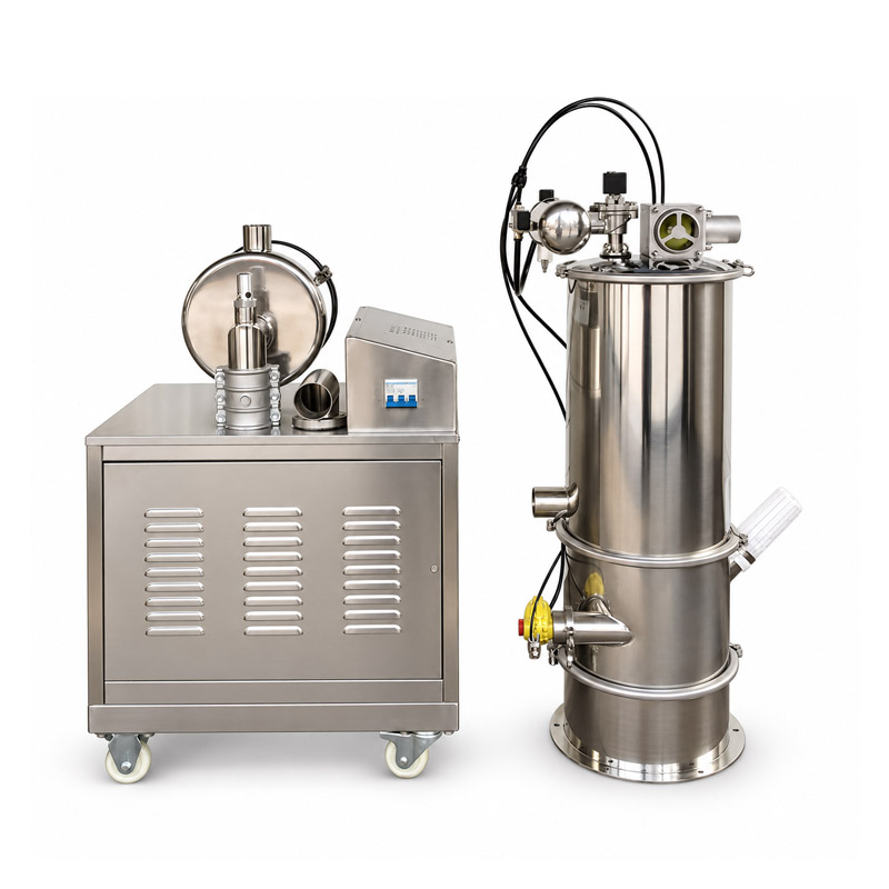
A vacuum feeder uses moving air to carry suitable powder or granules through a pipe into a receiver. A vacuum source lowers the pressure in the receiving system. Air entering at the pickup point moves toward that lower pressure and carries material with it. Inside the receiver, the material is separated from the air and released into the next container or process.
The word “vacuum” can make the movement sound mysterious. It is easier to imagine the air as the moving carrier. The pressure difference creates airflow, the airflow picks up material, and the receiver separates the two again. Understanding that sequence explains why a leak, a loaded filter, or a poorly supplied pickup point can interrupt transfer even when the vacuum source is running.
A complete cycle has several stages
Many compact vacuum feeders work in repeated cycles. First the discharge valve closes so the receiver can hold the required pressure difference. The vacuum source then draws air and material through the conveying line. Solids accumulate in the receiver while the air continues toward the filter and vacuum connection.
After a defined filling period or another permitted control signal, suction stops or the system changes state. The receiver is brought to the condition required for discharge, and the lower valve opens so the material can fall out. The valve then closes for the next filling stage. A filter-cleaning step may be included in the cycle, depending on the design.
That repeated sequence is why the outlet can deliver a series of batches rather than one perfectly even stream. An upstream pickup may appear active for several seconds and then pause. This can be normal cyclic operation. It becomes a problem when the following process needs steadier flow than the cycle or an intermediate holding arrangement can provide.
Follow the air and the powder separately
At the pickup point, material must enter a moving stream of air. Too little available material can leave the line moving mostly air. Too much material presented in an unsuitable way can make pickup unstable or lead to a dense accumulation that the system cannot move as intended. The pickup arrangement is therefore an active part of the transfer route.
Along the pipe, air and particles interact with the walls, bends, and each other. The exact movement depends on the conveying regime. Some systems keep material relatively dispersed in air, while others move it in denser formations. A compact vacuum feeder should not be assumed to use a particular regime solely because the product name contains “vacuum.”
At the receiver, the material must stop following the outgoing air. The receiver geometry allows much of the solid material to settle or separate, and the filter limits fine powder carryover toward the vacuum source. The collected material then needs a clear gravity discharge route. Each of these stages has to work for a complete transfer cycle.
The filter is part of the airflow route
A filter catches fine material that would otherwise continue with the air. As powder accumulates on it, resistance to airflow can increase. The vacuum source may still be operating, but less useful air can reach the pickup point. That is one reason the sound of a running pump cannot establish that conveying conditions are healthy.
Different powders create different filter conditions. A fine, cohesive material may load a filter differently from coarse, free-flowing granules. Moisture or oil in the material can change the way deposits form. Filter area, construction, and cleaning method must match the application; a filter is not simply a universal fabric bag that works identically for every powder.
When a system has a cleaning cycle, its purpose is to release accumulated powder from the filter according to the design. It does not remove the need for inspection or eventual maintenance. Cleaning effectiveness, damage, and the condition of seals still matter. Work on the filter must follow the shutdown, isolation, and exposure-control procedures appropriate to the material.
Why an air leak can reduce pickup
A leak gives air another route into the low-pressure system. Some of the airflow then enters through the leak rather than through the intended pickup point. Depending on its location and size, this can reduce the air available to entrain the powder or change the operating condition of the whole route.
Connections, access lids, discharge valves, and receiver seals are possible places to investigate when performance changes. A leak does not always make an obvious whistle. Its effect may show up as longer filling times, incomplete pickup, or a changed pressure reading. These symptoms are clues, not a reliable leak diagnosis by themselves.
The useful comparison is with a known normal cycle using the same material. Record the pickup behavior, fill duration, receiver discharge, and any permitted pressure or control readings. Do not tighten, open, or dismantle a connection while the system is operating. The safe inspection method depends on the equipment and its connected process.
Pipe length is more than a straight-line distance
A pipe route has horizontal sections, vertical lift, bends, and connections. All of them influence the pressure difference and airflow needed to move material. A route with many tight bends is not equivalent to a straight route of the same measured length. Changes at the pickup or discharge can also alter the result.
Particle behavior matters at bends. Fragile granules may break during impacts, while abrasive material can wear the pipe wall. A powder blend may not behave exactly like one uniform particle type. These possibilities explain why the shortest route is often worth considering, but they do not create a universal pipe size or bend radius suitable for every material.
If you sketch a conveying route, include the height changes and bends rather than drawing only the distance between rooms. Mark the pickup container, receiver, and point where the powder is used. A simple route sketch often makes a confusing transfer problem easier to understand without needing detailed engineering calculations.
An average rate is different from a filling rate
Consider an illustrative feeder that transfers 5 kilograms into its receiver during a 20-second filling stage. It then needs 10 seconds to discharge and reset. One complete cycle takes 30 seconds. If that behavior remains consistent, there are 120 cycles in an hour, corresponding to an average transfer of 600 kilograms per hour.
Dividing only by the 20-second filling stage would suggest 900 kilograms per hour, but that calculation ignores the time needed to finish the cycle. The example shows why a brief observation during suction can overstate the rate available to the next process. Real cycle timing may include additional control delays or cleaning stages.
The example is arithmetic, not a rating for a Dongheng model. Actual transfer also depends on material density, pickup conditions, route, filter behavior, and discharge. A meaningful test records complete cycles over a representative period rather than selecting the fastest few seconds of operation.
| Stage | What should happen | What may interrupt it |
|---|---|---|
| Pickup | Air entrains material into the line | Poor material presentation or unsuitable airflow |
| Filling | Solids collect while air leaves through filtration | Loaded filter or leakage |
| Discharge | Receiver releases material to the next step | Closed route or material bridging |
| Reset | Valves and controls return to filling condition | Incomplete valve movement or control interruption |
Containment does not follow from the name alone
An enclosed transfer route can reduce open handling, but containment depends on the pickup, receiver, filter, valves, and connections together. Powder can still escape during bag opening, filter changes, or receiver discharge if those steps are not controlled. The word “vacuum” does not establish a verified exposure level or an explosion-protection rating.
Some powders are hazardous or combustible, and their handling needs a material-specific assessment and suitable equipment. A general learning article cannot establish those requirements from a photograph or a powder's common name. For an unfamiliar substance, start with its documented properties and the site's approved handling arrangements.
The vacuum feeder product page helps identify a receiver and vacuum-source arrangement. For general background, the pneumatic conveying section of Wikipedia's conveyor overview introduces the wider equipment family. A vacuum feeder is easiest to understand by tracking the air route, the material route, and the timing that connects them.
Does the pump pull the powder directly through itself?
In a suitable receiver system, the powder is separated from the conveying air before that air reaches the vacuum source. The filter and receiver are central to that separation.
Why does the powder stop arriving for a few seconds?
A cyclic receiver may pause suction while it discharges and resets. Compare the observed sequence with the machine's normal control cycle.
Does stronger vacuum always mean faster transfer?
No. Useful conveying depends on airflow, material pickup, the pipe route, filtration, and discharge. A pressure reading alone does not establish delivery rate.
Can a vacuum feeder move every powder gently?
No universal claim is justified. Particle strength, bends, velocity, and the conveying regime affect damage and must be assessed for the material.
What should a basic performance record include?
Record the material, complete cycle time, measured mass transferred, route, pickup arrangement, and relevant operating conditions rather than only the pump setting.