
Table of Contents
A screw conveyor moves bulk material by rotating a helical blade inside a trough or tube. The blade pushes material along the enclosure. Gravity and friction help keep the material from simply rotating with the screw, so part of the motion becomes forward travel. The result is a continuous movement of powder, granules, or another suitable bulk solid toward an outlet.
The easiest comparison is a spiral ramp wrapped around a central shaft. Rotate that spiral while the surrounding material resists turning with it, and the spiral repeatedly advances the material. An actual conveyor is more complicated than that picture, especially when it is inclined or handling sticky material, but the picture explains why a rotating component can produce movement along a straight route.
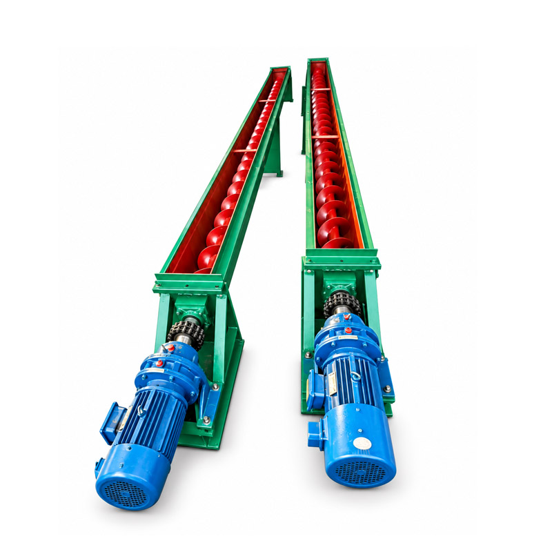
Identify the parts you can see
The screw consists of a shaft and flights, the curved blades that form the spiral. The distance from one turn to the next is called the pitch. The surrounding enclosure supports or contains the material route. A drive rotates the screw, while the inlet and outlet connect the conveyor to the equipment before and after it.
Bearings support the rotating assembly. Longer arrangements may include intermediate supports, depending on the design. Seals help manage the points where a shaft passes through the enclosure. Covers and guards keep people away from moving parts and help contain material, but the exact degree of dust containment depends on the complete arrangement, including its connections.
From the outside, a tube can conceal almost all of these working parts. That is why the visible outer diameter is not enough to explain performance. Two similarly sized housings can contain different screw diameters, pitches, clearances, speeds, and support arrangements. Those differences change how the material moves.
One rotation does not move every particle one pitch
In a simple drawing, it is tempting to imagine a particle advancing exactly one spiral turn during each revolution. Real bulk material slips, rearranges, and rubs against both the flights and the enclosure. Some particles move forward, some circulate locally, and some temporarily settle in spaces near the wall. The average forward movement is less tidy than the drawing.
This is particularly important when reading a theoretical capacity calculation. A geometric calculation describes the space available to move material. It does not prove that every part of that space stays filled or that all material moves forward without slip. Practical capacity depends on the material, the operating speed, the filling condition, and the installation.
A dry, free-flowing granule and a cohesive powder can behave very differently in the same conveyor. A fluffy powder also occupies more volume for a given weight than a dense granule. A machine that moves the same volume per hour therefore does not necessarily move the same weight per hour when the material changes.
The inlet decides how much material reaches the screw
There are two situations worth separating. In a conveyor that is fed at a controlled rate, another device limits the incoming flow. In a feeder arrangement, material may cover or flood the inlet and the screw itself helps determine how much is withdrawn. Those are different duties even when both machines contain a screw.
Imagine pouring flour into a narrow funnel faster than the outlet can accept it. The flour accumulates upstream. Making the downstream mechanism rotate faster does not automatically eliminate poor flow in the funnel. A similar distinction applies to a screw conveyor: a bridge in the hopper can starve the screw, while an excessive uncontrolled supply can overload the inlet region.
The shape and length of the inlet matter as well. A long opening beneath a storage hopper needs to withdraw material in a controlled way along its length. A simple constant-pitch screw is not automatically suitable for that task. The design must match the intended withdrawal pattern rather than relying on the word “conveyor” alone.
Why the enclosure changes the movement
A U-shaped trough offers a different arrangement from a closed tubular housing. The trough can make access for inspection and cleaning more straightforward when its covers are safely removed after isolation. A tube surrounds the screw more completely and may fit a compact transfer route. Neither shape alone establishes that the machine suits a particular powder or hygiene requirement.
Clearance between the flights and the enclosure has practical consequences. If hard particles become trapped in an unsuitable gap, they can wear or damage components. A sticky product can leave a coating on internal surfaces. A material that compacts readily may build resistance if the route or discharge is restricted. These effects are part of bulk-material behavior, not evidence that the basic spiral principle has stopped working.
The enclosure also needs a suitable outlet. If the receiving hopper fills and blocks discharge, material cannot keep advancing normally. The screw continues to apply force, but that force may compact material instead of delivering useful flow. Watching only the motor misses the cause at the receiving end.
Inclines introduce a backward influence
On a horizontal route, gravity mainly presses material downward into the enclosure. On an uphill route, gravity also encourages material to move back toward the inlet. More local recirculation and slip can occur, and the useful forward flow can fall. The size of that change depends on the material and the conveyor arrangement.
This is why a capacity stated for a horizontal machine should not be carried over unchanged to a steep incline. It is also why an enclosed screw should not be assumed capable of lifting material vertically. A vertical screw arrangement needs to be designed for its own operating conditions; it is not simply a horizontal conveyor stood on end.
Consider two transfer routes that reach the same height. One is short and steep, while the other is longer and less steep. The shorter route does not automatically require less power or produce a higher usable output. The material's tendency to fall back, the filling condition, and the discharge arrangement all influence the result.
Speed is only one control
Increasing rotational speed can increase theoretical movement, but the relationship between speed and useful output is not unlimited. At some conditions, material may tumble or rotate more instead of advancing efficiently. Higher speed can also change wear, particle damage, heating, and the behavior at the inlet.
For a fragile granule, the relevant result includes how much of it remains intact. For a powder blend, maintaining the intended mixture can matter as much as delivery rate. For an abrasive solid, the condition of the flights and enclosure becomes part of the operating picture. A useful description of performance therefore includes what arrives at the outlet, not just how fast the screw turns.
Speed changes should follow the manufacturer's permitted settings and the complete system's limits. Removing guards or working near a rotating screw is dangerous. Inspection and blockage clearing require the specified isolation procedure, including stored material and connected equipment that could restart or feed the conveyor.
Read a simple flow example
Suppose a conveyor delivers a measured 2 cubic meters of material per hour. If the material's measured bulk density is 500 kilograms per cubic meter under the relevant handling condition, the corresponding mass flow is 1,000 kilograms per hour. If another material has a bulk density of 800 kilograms per cubic meter, the same volume would correspond to 1,600 kilograms per hour.
These are arithmetic examples, not performance claims for a particular model. They show why a weight-based target needs a bulk-density value. They also show why the condition of the sample matters. A loosely filled powder may occupy a different volume from the same powder after vibration or settling.
The reverse calculation is equally useful for understanding a requirement. A target of 1,200 kilograms per hour at 600 kilograms per cubic meter corresponds to 2 cubic meters per hour. That converts the target into a volume flow, but it does not select the screw diameter or motor. Material behavior, inclination, filling, and the surrounding equipment still need evaluation.
| Observation | First question to investigate |
|---|---|
| Screw runs but little material leaves | Is material reaching the inlet consistently? |
| Material backs up near discharge | Can the receiving equipment accept the flow? |
| Output changes with a different powder | Did bulk density or flow behavior change? |
| Inclined route moves less than expected | Was the actual incline included in the assessment? |
Recognize the principle in a real transfer route
Dongheng's screw conveyor page illustrates the equipment family. When looking at any such arrangement, trace the storage point, the inlet, the screw route, and the receiving point in that order. A problem at either end can look like a problem inside the screw.
The general screw conveyor reference on Wikipedia is useful for identifying the mechanism and common terminology. For learning the principle, the essential relationship is simple: the rotating spiral applies force, the enclosure and material resistance prevent free rotation of the whole bed, and the resulting movement carries material forward. The practical details determine how well that happens for a particular material.
Is an auger conveyor the same thing as a screw conveyor?
The terms often describe the same general spiral conveying mechanism. Confirm the actual construction and intended duty when comparing equipment.
Can it move material uphill?
A suitably designed machine can, but inclination changes flow and loading. Horizontal capacity should not be assumed to remain available on an incline.
Does doubling speed double delivery?
Not necessarily. Filling, slip, inlet flow, and material behavior can prevent a simple proportional increase in useful output.
Why does the conveyor run partly empty?
Many conveying duties use only part of the available cross section. A partly filled enclosure is not automatically evidence of a fault.
Why do weight and volume ratings differ?
Weight flow depends on bulk density as well as volume flow. Powders with different densities can have different mass outputs at the same volumetric rate.